Astable 555 Timer Schematic - 555 Timer Astable Circuit Calculator - Electrical ... - This means that the output voltage is a periodic pulse that alternates between the vcc value and 0 volts.
Astable 555 Timer Schematic - 555 Timer Astable Circuit Calculator - Electrical ... - This means that the output voltage is a periodic pulse that alternates between the vcc value and 0 volts.. If ton is the time for high output and t is the time period of one cycle, then the duty cycle d is given by: D = ton/ t therefore, percentage duty cycle is given by: See full list on electronicshub.org In order to achieve pulse position modulation, two 555 timer ic's are used in which one operates in astable mode and the other in monostable mode. It is best to choose c1first (because capacitors are available in just a few values and are usually not adjustable, unlike resistors) as per the frequency range from the following table.
The duty cycle of an astable multivibrator is always greater than 50%. The output of the timer at this point is low. A collection of 555 circuits using the 555 timer as an astable oscillator with different duty cycles. It is best to choose c1first (because capacitors are available in just a few values and are usually not adjustable, unlike resistors) as per the frequency range from the following table. See full list on electronicshub.org
555 Timer Basics - Monostable Mode from i2.wp.com See full list on electronicshub.org The 555 timer is a chip that can be used to create pulses of various durations, to output a continuous pulse waveform of adjustable pulse width and frequency, and to toggle between high and low states in response to inputs. The schematic of the ic 555 as an astable multivibrator along with the three external components is shown below. 555 timer calculator overview the 555 timer shown above is configured as an astable circuit. Duty cycle is the mathematical parameter that forms a relation between the high output and the low output. Complete 555 timer circuit reset switch. See full list on electronicshub.org The ic 555 can be made to work as an astable multivibrator with the addition of three external components:
Choose r2 to give the frequency (f) you require.
Pin 1 connects to 0v. Complete 555 timer circuit reset switch. The value of ton or the charge time (for high output) tcis given by: The following schematic depicts the internal circuit of the ic 555 operating in astable mode. See full list on electronicshub.org One diode in parallel to the resistor r2 with cathode connected to the capacitor and another diode in series wi. The modulating signal is applied at the pin 5 of the first ic 555 that is. Generally, the charging time constant is more than the discharging time constant. Jul 27, 2021 · the 555 timer shown above is configured as an astable circuit. The position of the each pulse changes according to the instantaneous samples voltage of the modulating signal. The formulas below will tell you the length of the output's on and off cycles with different resistors and capacitors: This means that the output voltage is a periodic pulse that alternates between the vcc value and 0 volts. A collection of 555 circuits using the 555 timer as an astable oscillator with different duty cycles.
Ton = tc = 0.693 * (r1 + r2) c the value of toff or the discharge time (for low output) tdis given by toff = td = 0.693 * r2c therefore, the time period for one cycle t is given by t = ton. The modulating signal is applied at the pin 5 of the first ic 555 that is. It is best to choose c1first (because capacitors are available in just a few values and are usually not adjustable, unlike resistors) as per the frequency range from the following table. See full list on electronicshub.org Duty cycle is the mathematical parameter that forms a relation between the high output and the low output.
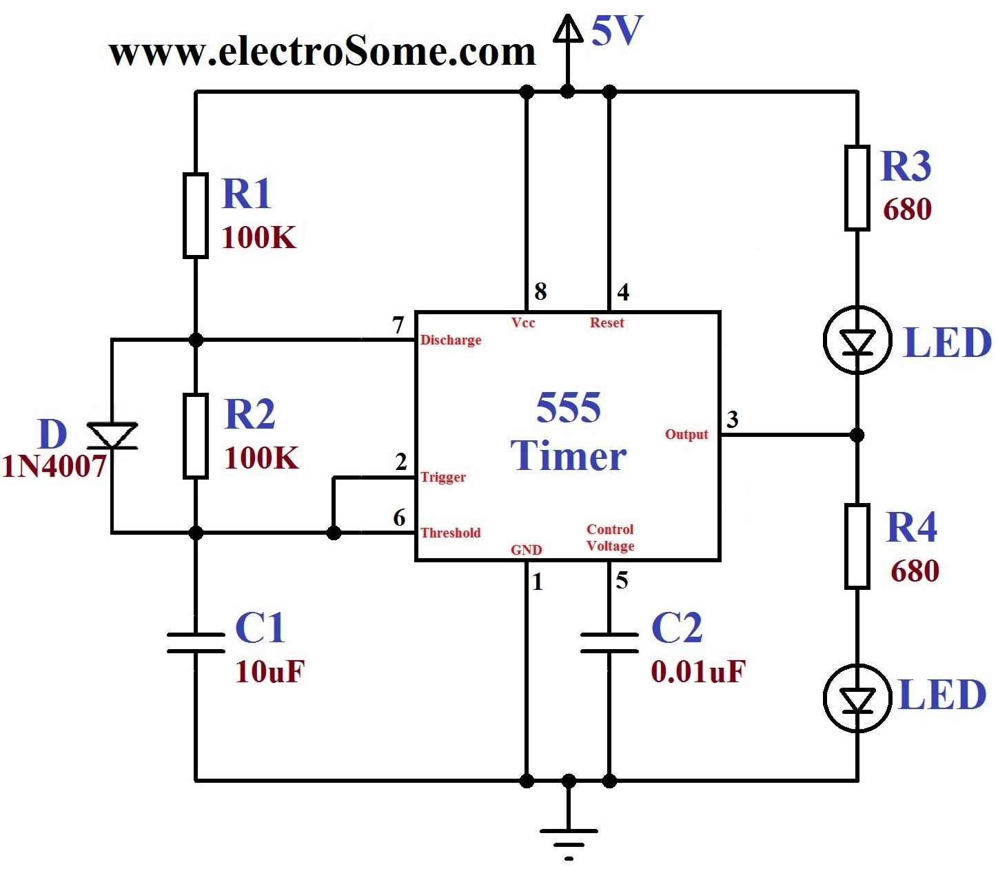
Dancing Light using 555 Timer from electrosome.com This means that the output voltage is a periodic pulse that alternates between the vcc value and 0 volts. See full list on electronicshub.org The pins 2 and 6 are connected and hence the. One diode in parallel to the resistor r2 with cathode connected to the capacitor and another diode in series wi. The following schematic depicts the internal circuit of the ic 555 operating in astable mode. Feb 18, 2021 · 555 circuits part 1. The rc timing circuit incorporates r1, r2and c. In astable mode, capacitor c1 charges through resistors r1 and r2.
The charging and discharging time constants depends on the values of the resistors r1 and r2.
Generally, the charging time constant is more than the discharging time constant. If ton is the time for high output and t is the time period of one cycle, then the duty cycle d is given by: See full list on electronicshub.org %d = (ton/ t) * 100 t is sum of ton (charge time) and toff(discharge time). The position of the each pulse changes according to the instantaneous samples voltage of the modulating signal. This means that the output voltage is a periodic pulse that alternates between the vcc value and 0 volts. See full list on electronicshub.org Duty cycle of 50% or anything less than that is not possible with the ic 555 as an astable multivibrator mentioned above. The value of ton or the charge time (for high output) tcis given by: Using 555 timer ic, we can generate precise time duration of high and low output, from micro seconds to hours, that's why 555 is very popular and versatile ic. 555 timer calculator overview the 555 timer shown above is configured as an astable circuit. Jul 28, 2021 · the 555 timer ic has been around now for quite some time and the list of potential. May 06, 2020 · in astable mode, the 555 timer acts as an oscillator that generates a square wave.
Complete 555 timer circuit reset switch. If ton is the time for high output and t is the time period of one cycle, then the duty cycle d is given by: It has no stable states and continuously switches between the two states without application of any external trigger. D = ton/ t therefore, percentage duty cycle is given by: A square wave is obtained as the output of an astable multivibrator when the duty cycle is 50% exactly.
Astable Multivibrator using 555 Timer from www.circuitstoday.com May 06, 2020 · in astable mode, the 555 timer acts as an oscillator that generates a square wave. The selection of values of r1, r2 and c1for different frequency range are as follow: See full list on electronicshub.org The general 555 timer circuit schematic at the heart of the circuit is a lm555 ic, which includes 23 transistors, 2 diodes and 16 resistors on a silicon. The formulas below will tell you the length of the output's on and off cycles with different resistors and capacitors: The value of ton or the charge time (for high output) tcis given by: Hence the high output remains longer than the low output and therefore the output waveform is not symmetric. D = ton/ t therefore, percentage duty cycle is given by:
One diode in parallel to the resistor r2 with cathode connected to the capacitor and another diode in series wi.
The value of ton or the charge time (for high output) tcis given by: What is a 555 integrated circuit? By using a potentiometer in place of r2, a train of pulses can be generated with different widths. The formulas below will tell you the length of the output's on and off cycles with different resistors and capacitors: The selection of values of r1, r2 and c1for different frequency range are as follow: The schematic of the ic 555 as an astable multivibrator along with the three external components is shown below. Generally, the charging time constant is more than the discharging time constant. The modulating signal is applied at the pin 5 of the first ic 555 that is. Sep 29, 2015 · astable mode works as a oscillator circuit, in which output oscillate at a particular frequency and generate pulses in rectangular wave form. The position of the each pulse changes according to the instantaneous samples voltage of the modulating signal. The ic 555 can be made to work as an astable multivibrator with the addition of three external components: See full list on electronicshub.org In order to achieve pulse position modulation, two 555 timer ic's are used in which one operates in astable mode and the other in monostable mode.
By using a potentiometer in place of r2, a train of pulses can be generated with different widths 555 timer schematic. Duty cycle is the mathematical parameter that forms a relation between the high output and the low output.


0 Komentar